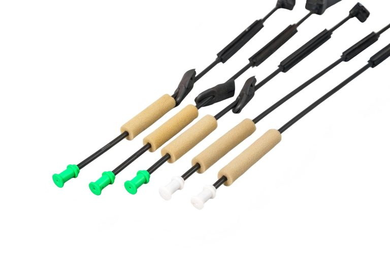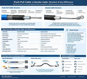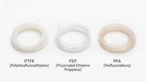
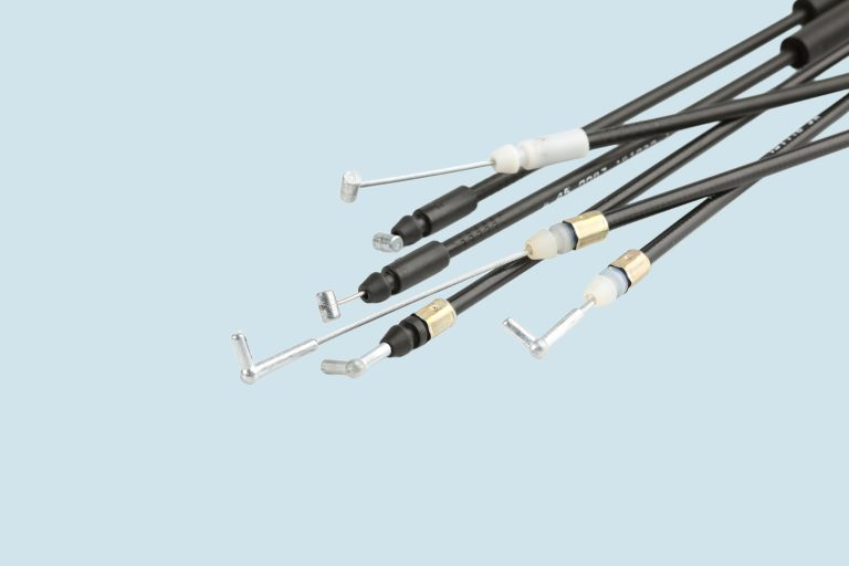
Push pull cable end fittings are crucial structural components that link flexible control cables to levers, actuators, mechanisms or mounting brackets to convey mechanical action.
How the end fittings attach to the inner wire, outer sheath and mounting interface. When choosing fittings, consider these. Each part must be compatible with the type of cable assembly both in terms of size and in terms of operation. Only when all components are compliant with the cable assembly’s size and operational criteria can they be joined into the fully functional control cable components and assure stable, dependable control system operation.
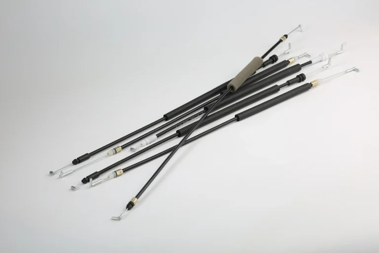
How Push-Pull Cable End Fittings Work
End fittings and connectors are used to connect the cable assembly (inner member and conduit) mechanically to the driving mechanism, lever, or mounting bracket.
In a push-pull control system, force transmission requirements depend on the direction of movement:
Pulling Force: The inner member and its end connection must withstand the required tensile load.
Pushing Force: Push capability depends on the inner member's construction, unsupported length, conduit support, and mounting arrangement. Inadequate support may cause buckling or inconsistent motion transfer.
Push performance is influenced by the inner member construction, unsupported length, and conduit restraint. If support is inadequate, buckling or unstable motion transfer can occur. Push-pull performance varies significantly among different assembly designs and must be evaluated based on the overall structure.
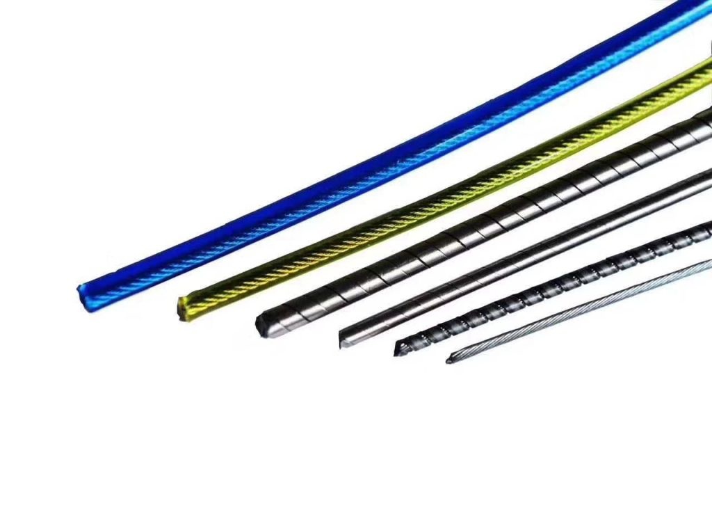
Types of Push Pull Cable End Fittings
The following are common fitting and mounting styles used across different cable-control designs. Not every type is suitable for every push-pull cable assembly:
Clevis Terminals (Fork Ends)
Normally, the U-shaped fork ends are attached to a rocker arm or linkage by a pin to form a hinged joint. Choose by assessing the accuracy of pin alignment, probable lateral loads, and swing range permitted by the installation space.
Eyelet & Loop Terminals
Eyelet terminals have a ring shape and are usually secured with bolts or pins. Their structure is generally simple and suitable for applications that transmit motion through a fixed connection point. During selection, evaluate fit clearance, bolt specifications, and installation space.
Ball Joints and Ball Shanks
Ball joint connections allow multi-directional angular misalignment within the design limit and are suited for compound motion systems or small angular variations. The permissible swing angle is dependent on the particular design of the ball stud and housing.
Threaded Terminals & Rods
Threaded terminals facilitate fixation and allow assembly length adjustment within the design allowance. Selection should focus on thread specifications, effective engagement length, locking method, and load requirements to ensure a stable connection.
Bulkhead Mounts and Conduit Retainers
Bulkhead mounts and conduit retainers are used to anchor the cable's outer conduit to a frame, bulkhead, or machine housing, providing the necessary conduit restraint for the cable assembly so that inner-member motion can be transmitted effectively.
Inner-Member Fittings vs. Conduit Mounts
When considering the connection structure of a cable assembly, it is necessary to make a clear distinction between the functional roles of inner-member end fittings and conduit mounts:
Inner-Member End Fittings: These are the fittings which connect the inner member directly to the driven mechanism (clevis terminals, eyelets, ball joints and threaded terminals) and transmit motion and load to the actuator.
Conduit End Fittings / Retainers: Locks the outer conduit or sheath (bulkhead mounts, conduit retainers), restricts axial movement and provides the necessary response support for the system.
Effective stroke loss or irregular action may take place regardless of whether the end fittings of the inner-member are intact, when the conduit is not properly fixed, or if there is installation displacement.
Key Factors When Selecting Cable End Fittings
End fittings are not separately selectable from the cable assembly. Even if the dimensions are compatible, the inner-member connection, conduit mounting, stroke and load need to be checked for compatibility. In the design stage it is advisable to address the following issues in a comprehensive manner:
Load and Movement Requirements: Review the projected tensile or compressive loads, operating stroke and movement direction. Assemblies, inner members, conduits, and mounting points must work together under the expected operating circumstances.
Stroke, Clearance and Lost Motion: The range of motion at the output end may differ from the range of motion applied at the input end. Lost motion can be caused by clearance between the inner member and conduit, conduit bending deformation, loose mounting points, and movement at end connections.
The selection of end fittings should also be based on the installation geometry, the cable assembly tolerances in addition to the operating stroke required. A properly coupled statically accurate fitting can still stop motion, provide too much slack, or interfere with surrounding parts throughout the whole stroke range.
Installation Space and Geometry: Check the connector’s external size and the motion path of the mounting interface to ensure that the connector will not interfere with other components within the entire stroke range.
Material Selection: Material selection should be considered for load, operating temperature, chemical exposure and dimensional stability. Different grades and environments yield different performances for engineering plastics. Material name does not determine applicability.
Evaluating whether your application relies on a simple one-way pull design or a complex two-way system—for example, by analyzing the structural differences in push-pull cable vs bowden cable—can help further determine the required structural stability of the end fitting.
Installation Factors That Affect Cable Movement
In actual installation and operating conditions, the smoothness of control cable movement is affected by the following installation factors:
Connection Interface Fit: Loose mounting points and excessive clearance at connection interfaces can contribute to lost motion. Loose mounting points or excessive fit clearance at interfaces are common causes of system play.
Routing and Conduit Support: Cable routing, conduit deformation and friction can also affect the amount of movement that reaches the mechanism. The routing shall be kept within the minimum bend radius indicated and the outside conduit shall be appropriately supported. Sharp bends, deformation of the conduit or increased internal friction can affect the smooth operation.
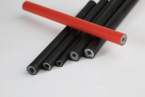
Choosing the right construction for a conduit and employing a proper push-pull cable conduit can help to keep the conduit stable in the long term and reduce conduit deformation under load.
Information Needed for Custom Cable End Fittings
For an OEM project, the following information can help define the required end fitting and its interface with the cable assembly:
Connection geometry: Mounting style, hole or thread dimensions, pin size, and available installation space.
Movement requirements: Operating stroke, movement direction, and required angular movement at the connection.
Load conditions: Expected push and pull loads under the intended operating conditions.
Cable interface: Inner-member construction, conduit dimensions, and component retention methods.
Operating environment: Temperature, exposure to moisture or chemicals, and other application-specific conditions.
Drawings or samples: Dimensional drawings, interface specifications, or an existing component for reference.
These details help establish the initial design requirements. Final fitting selection should be checked against the complete cable assembly and its intended operating conditions.
Custom Pull Cable Connectors for OEM Applications
For OEM industrial projects requiring specific mounting interfaces and non-standard geometries, KELI specializes in custom development services for pull cable connectors, producing custom connectors through injection molding to meet customized production needs.
Custom Structural Features: We can custom-develop dedicated connection structures including special buckles, cross-heads, and locking structures according to customer equipment interface requirements.
Engineering Plastics Evaluation: The selection of engineering plastics such as PA (nylon), POM (polyoxymethylene, also known as acetal), and PBT can be determined by the connector design, load, operating conditions, and moulding specifications. Material grade is decided according to the actual application requirements.
Typical Applications Listed on the Official Website: Typical applications listed on the official website include door locks, hood release, seat adjusters, and fuel cap release control systems.
For OEM customers seeking push pull cable end fittings solutions that match a specific mounting interface, KELI can provide customized pull cable connector solutions based on specific application requirements and cable assembly design.