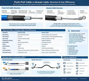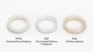
A push-pull cable conduit must transmit movement reliably while protecting the inner cable. Excessive compression, repeated bending, or internal wear can increase operating force and reduce effective stroke.
For OEM engineers, a push-pull cable compression test helps evaluate deformation under a defined load. A cable conduit fatigue test checks whether the conduit and cable assembly maintain their performance after repeated movement. These tests measure different failure risks. Neither alone proves that a cable system will meet its service-life requirements.
This guide explains how to test compression resistance, evaluate fatigue performance, measure force-stroke changes, and establish application-specific acceptance criteria. The goal is to help engineers select and validate a suitable conduit for real operating conditions.
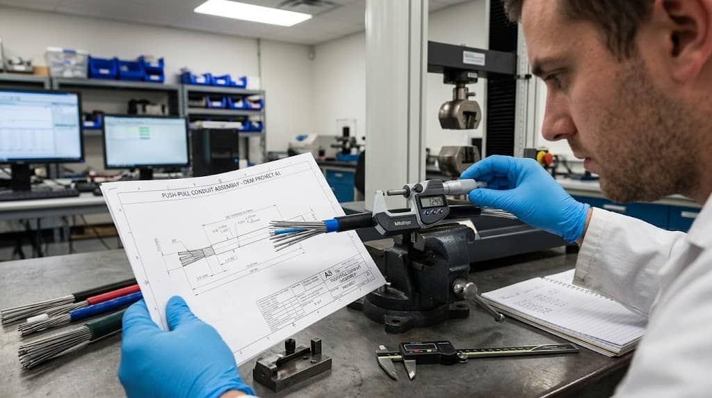
Define the Test Requirements
Before testing, identify the loads, movements, environmental conditions, and expected service life of the application.
| Parameter | What to specify |
| Conduit construction | Liner, reinforcement, outer jacket, and materials |
| Dimensions | Inner diameter (ID), outer diameter (OD), and length |
| Operating load | Normal and peak push-pull forces |
| Stroke | Required input and output travel |
| Routing | Installation path, bend radius, and mounting points |
| Environment | Temperature, moisture, oils, and other relevant exposure |
| Service life | Expected operating cycles and duty cycle |
| Acceptance criteria | Allowable deformation, force change, stroke loss, and damage |
Use production-representative samples whenever possible. Material, dimensions, reinforcement, and end fittings should match the intended assembly.
Also define whether the test evaluates the conduit alone or the complete cable assembly. A standalone conduit test can assess structural behavior, but it cannot fully reproduce friction, alignment, and stroke transmission in an installed system.
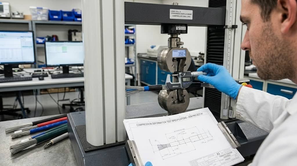
How to Perform a Push-Pull Cable Compression Test
A push-pull cable compression test evaluates how a conduit responds to a specified compressive load. The objective is to identify excessive deformation that could affect internal clearance, cable movement, or system performance.
Step 1: Measure the initial dimensions.
Record the initial OD and, where accessible, ID at defined positions. Inspect the liner, reinforcement, and outer jacket for visible defects. Use the same measurement locations throughout the test.
Step 2: Apply a controlled load.
Secure the sample in a suitable fixture. Apply the specified load in the direction relevant to the application.
Distinguish between external crushing, local clamping pressure, and axial compression generated during push operation. These conditions produce different stress patterns and should not be treated as equivalent. Record the load, loading rate, dwell time, fixture arrangement, and test temperature.
Step 3: Measure deformation under load.
Record changes in diameter, local flattening, or axial shortening, depending on the test objective. For diameter reduction, calculate:
Diameter deformation (%) = [(D₀ − D₁) / D₀] × 100
Where:
- D₀ = initial outside diameter
- D₁ = outside diameter under the specified load
This formula measures diameter reduction only. It does not quantify axial compression or establish the assembly's ability to transmit its required stroke.
Step 4: Check recovery after unloading.
Remove the load and measure the sample after a defined recovery period. Compare the final dimensions with the baseline measurements.
Permanent deformation, cracks, liner damage, or reinforcement displacement may indicate a potential design or installation problem. Record both the immediate response under load and the residual deformation after unloading. These measurements help distinguish temporary deformation from permanent dimensional change.
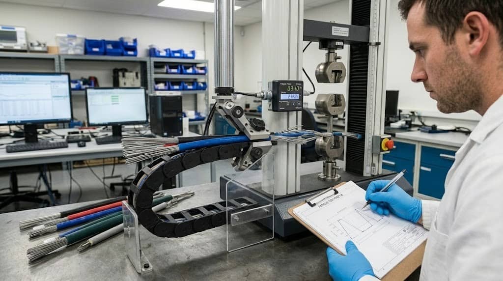
How to Conduct a Push-pull Cable Conduit Fatigue Test
Fatigue testing evaluates a cable conduit’s performance over repeated movement or loading, as well as changes in performance, wear, and potential damage over the life of the product. This testing also helps identify changes in the operating behavior of a conduit that may not be evident through a single compression test.
Step 1: Reproduce the installation path
The conduit is installed to the specified bend radius, with the mounts and end connections. The intended internal cable is loaded in the conduit when testing the completed assembly. A straight sample may not reveal problems caused by tight bends, misalignment, or friction along the actual cable route.
Step 2: Define movement cycle
There must be a definition of the stroke length, the direction of movement, the speed and frequency of movement, as well as the load profile. For bidirectional systems, both the push and the pull loads must be specified.
There must be a determination of the environmental conditioning for the validation plan, based on the expected changes in the service environment, e.g., temperature and fluid exposure.
Step 3: Carry out the defined cycles
The assembly must be operated to the defined conditions, and changes in stroke, noise, and the physical condition of the assembly must be documented. Changes in the number of cycles the assembly is operated to may also affect functional performance.
Step 4: Inspect the assembly after cycling
The liner, reinforcement, jacket, cable, and end fittings must be inspected for abnormal wear, cracking, abrasion, and deformation. Determine the number of cycles completed, when the first observable damage occurred, and the functional performance limit beyond which the operation of the assembly was no longer acceptable.
Measure Force-Stroke Performance Before and After Testing
Compression resistance and fatigue life do not fully describe cable performance. The assembly must also deliver the required output movement without excessive operating force.
Measure input and output stroke under consistent loads, routing conditions, and measurement points.
Stroke transmission efficiency (%) = (Output stroke / Input stroke) × 100
Use the same measurement method before and after durability testing. Where appropriate, record the force required across the full stroke rather than relying on a single reading.
| Measurement | What it reveals |
| Initial operating force | Baseline system resistance |
| Force during movement | Changes in friction or binding |
| Input stroke | Movement supplied by the actuator |
| Output stroke | Movement delivered to the mechanism |
| Stroke efficiency | Proportion of input travel transferred to output |
| Force-stroke curve | Changes in resistance across the movement range |
An increase in operating force may indicate liner wear, contamination, misalignment, or changes in routing. Reduced output stroke may result from casing deformation, movement loss, or connection problems.
Interpret these results together. A force increase alone does not establish the root cause.
Compare Dimensions and Functional Performance
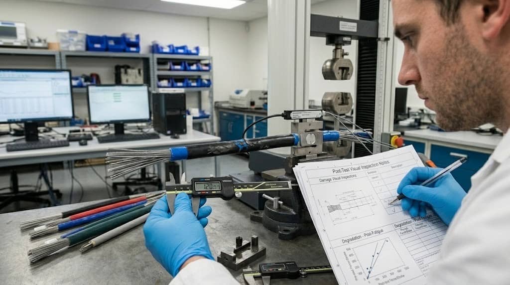
A reliable cable conduit testing procedure combines dimensional inspection with functional measurements.
| Inspection item | Before testing | After testing |
| Conduit ID and OD | Establish baseline dimensions | Identify dimensional changes |
| Outer jacket | Check surface condition | Inspect abrasion and cracks |
| Reinforcement | Check construction and position | Identify displacement or damage |
| Cable movement | Record initial operating behavior | Check for binding or resistance |
| Operating force | Record force across the stroke | Quantify changes |
| Stroke transmission | Measure input and output travel | Identify increased stroke loss |
| End fittings | Check mounting and retention | Inspect movement or loosening |
Keep the measurement method, fixture, and relevant environmental conditions consistent. Record measurement uncertainty when small dimensional changes could affect the conclusion.
For OEM projects, this comparison provides a practical basis for identifying whether a conduit design maintains its dimensions and functional performance under the intended conditions.
How to Establish Acceptance Criteria
There is no universal compression limit or fatigue cycle count suitable for every push-pull cable conduit. Acceptance criteria must reflect the application, product construction, customer requirements, and validated design limits.
Define measurable limits for:
- Maximum deformation under the specified compressive load.
- Maximum permanent deformation after unloading.
- Allowable changes in operating force.
- Minimum acceptable output stroke or stroke transmission efficiency.
- Required cycle count and post-test functionality.
- Permitted surface damage and end-fitting movement.
Standards can be used to help establish the appropriate test methods, but the scope of the standard must be checked before applying the requirements to a specific product. For example, IEC 61386-1 addresses conduit systems for electrical installations and for communications applications. Its requirements shall not be used as acceptance criteria for mechanical push-pull control cable conduit.
Further technical references are ABB’s explanations of conduit compression strength testing and continuous-bending fatigue testing. These resources illustrate testing methods rather than a universal pass/fail threshold for all mechanical cable assemblies.
Select the Right Conduit for the Application
Test results should guide product selection. It is not always best to have a stiffer conduit, as performance is also affected by reinforcement, liner properties, bend radius and installation geometry.
The Keli Push-Pull Outer Casing can be evaluated for applications where reliable push and pull movement against the required load, stroke, routing, friction and durability conditions are needed.
Keli Armoured Cable Outer Casing provides a multi-layer reinforced conduit solution for applications where additional mechanical protection is needed. It should be checked for suitability against the required dimensions, flexibility, environmental exposure and functional performance.
For wider design considerations, see How to Choose the Right Push-Pull Cable Conduit for OEM Applications.
For custom projects, provide the manufacturer with drawings, samples, operating loads, cable routing, environmental conditions and service-life goals. This information supports the creation of a test plan based on the actual application.
Frequently Asked Questions
Q1. What is a cable push-pull compression test?
It measures the reaction to a specified compressive load of a conduit or a complete cable assembly. Depending on the setup, measurements may include diameter reduction, axial shortening, residual deformation, and change in functional movement.
Q2: How do you test the fatigue life of cable conduit?
Repeatedly manipulate the conduit or assembled cable under a specified stroke, load, bend radius, and applicable environmental conditions. Acceptance limits for recorded cycle count, functional change, and damage or failure.
Q3: Does compression testing demonstrate fatigue resistance?
No. Compression testing tests the response to a known load. Fatigue testing determines performance under repeated movement or loading. Both may be needed to assess different risks of failure.
Q4: What causes the increase in the operating force after the fatigue testing?
Possible causes could be liner wear, contamination, misalignment, reinforcement damage, or changes to cable routing. The actual reason should be looked into.
Q5: How many cycles should a cable conduit be subjected to?
The number of cycles required varies with the application, operating frequency, load, stroke, bend radius and expected life. The best way is to define the target before testing, not to use an unsupported universal value.
Conclusion
A reliable push-pull cable conduit must be able to withstand the effects of compression loads and repeated movement on its structural integrity and functional performance. A combination of a push-pull cable compression test, a cable conduit fatigue test, force-stroke measurements, and before-and-after dimensional inspections makes for a more complete assessment than any one test.
For OEM applications, the most useful validation plan reflects the actual installation and uses measurable, application-specific acceptance criteria. Keli can look over technical drawings, samples, and operating requirements to help determine the correct push-pull or reinforced conduit setup.
Looking for a custom cable conduit? Contact Keli to discuss your technical requirements and product validation needs.